« first day (591 days earlier)      last day (2328 days later) » 
01:00 - 12:0012:00 - 18:00

01:27
@sammygerbil are you on holiday still? Do you have some free time
 
1 hour later…
02:52
9 hours ago, by sammy gerbil
@Abcd I've decided to leave on Wednesday morning instead of tomorrow morning.
@sammygerbil Sorry I had fallen asleep
@sammygerbil I have not understood this perfectly...facing some problems... Let me see if JR can explain with diagram or something.
@JohnRennie Morn.
 
1 hour later…
04:00
@JohnRennie morning!
@Jasmine morning :-)
I need help in understanding number of images formed.
This is a simple thing but i didnt get.
OK ... ?
Lets consider two mirrors kept parallel to each other then infinite number of images should be formed?
04:03
By the logic that each image formed by one mirror will act as object for other.
But in lenses we do not consider the intermediate images to be images why?
With lenses the light is basically moving in a straight line i.e. along the optic axis. Yes there are deviations from this, but in general they are small and the whole system is effectively one dimensional.
The light starts at one end and ends up at the other.
@JohnRennie yes
@Jasmine That's a bit different. In effect the two halves of the lenses with different refractive indexes act as two different lenses forming images in different places.
04:08
In this question i thought that the image formed by the first surface of the lens will act as object for the 2nd surface but in the answer that image for 1st surface is not considered as image
You mean you treated the lens as if it were made up of two half lenses (curved on only one side)? If so, then that's a perfectly good way to do the calculation.
@JohnRennie yes
@JohnRennie ???
Although you don't need to do two calculations. Just calculate the focal ength of each half lens then use $1/F = 1/f_1 + 1/f_2$
@Abcd morning :-)
@JohnRennie but i am supposed to find only the number of images not location
Consider the region below $µ_4$ to be air.
04:14
Ah, OK, so you're asking why the image produced by the first half lens, and then used as the object for the second half lens, isn't included in the number of images?
@JohnRennie yes!
@JohnRennie In Newton's ring, why is reflection from first surface of glass lens ignored??
@Jasmine With lenses an image is the place where the light rays converge, or with virtual images the place where light rays would converge if we extended them backwards.
The "image" formed by the first half lens is just a computational device. The light rays don't actually converge there.
@Abcd you remember that problem yesterday with the thin film on the glass plate - we only included reflection at the air-film and film-glass interfaces?
@JohnRennie ya
As a general rule when optical elements get thick it's hard for them to generate interference. After all you don't see interference from the panes of glass in house windows.
04:22
@JohnRennie ok! As the rays actually bend at the second surface and not they actually seem to converge at the virtual object we obtained as image from 1st surface?
@Jasmine basically yes.
So in this case the answer should be 3?
@JohnRennie how does that imply that we shouldnt consider reflection from first surface
@Jasmine I would say three, because you effectively have three lenses with different focal lengths present. I hope you're not now going to tell me the answer isn't three :-)
@JohnRennie thank you! I got it finally. Although it was a silly doubt..
04:26
@Abcd In the Newton's rings we get interference where the air gap is very small i.e. where the spacing between the flat plate and the bottom surface of the lens is small.
So we just consider those two surfaces.
The top side of the lens is typically too far away to contribute to the interference.
@Jasmine cool :-)
@JohnRennie But still it must be having some effect
What effect does it cause?
I don't think it has any measurable effect.
As to what effect it would have with a perfect lens and perfect measuring equipment, I'm not sure.
10 hours ago, by Abcd
user image
10 hours ago, by Abcd
user image
9 hours ago, by Abcd
user image
@JohnRennie Please help w/ this question.
You and Sammy discussed that fairly thoroughly. What aspects of it are still unclear?
9 hours ago, by sammy gerbil
@Abcd Sorry I misunderstood this comment. When the source slit is close, the light from it is not incident normally on the double slits. Light from the source is incident at an upward angle relative to the horizontal on the upper slit and at a downward angle on the lower slit. As the source moves closer these angles get bigger.
@JohnRennie This message ^ (I had fallen asleep when he sent this so couldn't ask him that time)
04:39
That angle shouldn't make any difference
@JohnRennie Then dont you think answer should be A and C?
If the slits are small compared to the wavelength of the light then they just behave as point sources and the angle of the light incident on them doesn't matter.
5 mins ago, by Abcd
9 hours ago, by Abcd
user image
@JohnRennie ya, that's how it appears from this diagram^
1 min ago, by Abcd
@JohnRennie Then dont you think answer should be A and C?
In practice the light intensity falls with increasing angle so the intensity of the pattern will fall with increasing angle, but that's all.
@JohnRennie Seriously not getting ...
04:42
Consider a single slit with light incident on it e.g. the leftmost slit in your diagram.
Yes, $S_0$
If the slit is much much smaller than the wavelength of the light then it behaves just like a point source. It radiates light uniformly in all angles.
@JohnRennie spherical wavefronts right??
Like the red stuff shown?
@Abcd Yes. If the slit is much, much larger than the wavelength of the light then obviously it doesn't radiate light uniformly. You just get a bright line of the screen.
@JohnRennie ikr
@JohnRennie yes
04:46
And in between, e.g. when the slit width is about the same as the wavelength of the light, it behaves approximately as a point source but the intensity of the light it produces has some dependence on angle.
@JohnRennie didn't get.
Let me draw a diagram ...
Ok, Ill wait
For a perfect point source the intensity is not a function of angle so $I(\theta) =I(0)$.
@JohnRennie Just a minute, please listen. Urgent thing.
04:55
And a very narrow slit gets very close to this.
@Abcd yes?
@JohnRennie As we can clearly see, no interference on screen happens when diffraction is done without convex lens right?
Huh?
A Youngs slits expt produces a pattern with no lens present ...
I am talking about single slit diffraction
@Abcd a single slit does produce a diffraction pattern with no lens present
@JohnRennie How??
05:00
I think I've answered a question on that on the main site. Let me have a quick search ...
3
A: Derivation of the fraunhofer diffraction formula

John RennieLet's draw a diagram of the light hitting the slit and being diffracted by some angle: The light ray at the bottom of the slit has a phase lag, $\phi$, compared with the ray at the top of the slit because it has to travel farther. Let's assume that the angle happens to be the one where the pha...

I'm just going to make a coffee - I'll be a couple of minutes.
@JohnRennie I agree that there will be phase difference but I dont get how those two parallel rays can intersect on screen.
The distance to the screen is much much greater than the size of the slit, so while it's true that perfectly parallel rays can't intersect they need only deviate by a tiny angle to intersect. So we can treat them as approximately parallel.
@Abcd don't know
I've seen the experiment done - admittedly with a laser not with sunlight - and the single slit produces a diffraction pattern without needing a lens.
@Abcd Ah, OK, I see why a lens is being used.
You said, quite correctly, that parallel rays don't converge so they can't intersect.
@JohnRennie Now I dont understand why your experiment, done without the lens gave the right result.
Another way of putting it would be that the rays converge at infinity, so if we put a screen at infinity we would get the diffraction pattern (I know this is a dubious argument but bear with me).
The diffraction pattern I calculate in that answer is called the Fraunhofer diffraction pattern and strictly speaking it is only observed at infinity.
@JohnRennie I am aware that for Fraunhofer diffraction: $I(\theta)= \dfrac{\sin^2\beta}{\beta^2}$
At close distances we still get a diffraction pattern but it's a different pattern called the Fresnel diffraction pattern.
05:22
Where $\beta = \dfrac{\pi b \sin \theta}{\lambda}$
@JohnRennie Oh, we dont have the math of Frsenel diffraction in our syllabus.
So if we put the screen at a finite distance from the slits (or whatever) then the pattern we get is a Fresnel pattern not a Fraunhofer pattern. We still see a diffraction pattern but it's slightly different.
But ...
(a) for any sensibe screen distance the difference between the Fresnel and Fraunhofer patterns are negligibily small.
@JohnRennie Okay, now lets return to the question.
31 mins ago, by John Rennie
user image
@JohnRennie I even think this diagram is wrong.
(b) a lens focuses parallel rays at a distance $f$ (its focal length) so effectively the lens makes the distance $f$ equal to infinity i.e. with a lens we get a Fraunhofer pattern at the finite distance $f$.
Because for diffraction wont you need at least two wavelets?
That's why you sometimes see lenses used in experiments on diffraction. It's to make the Fraunhofer pattern visible at a non-infinite distance.
I need to work for ten minutes or so ...
05:29
please tell when you are back.
05:40
@Abcd back
Diffraction occurs when the light from two point sources intersects. In the YDSE we treat the two slits as two point sources.
But a light wavefront is an infinite array of point sources and they all interfere with each other. This is the basis of the Huygens'-Fresnel principle.
In a single slit of non-zero width the diffraction pattern is formed by the infinite number of point sources that span the width of a slit.
@sammygerbil It's a part of a continuous circuit. As the currents and directions are given, I applied KCL and found the values of current flowing across the two resistors of branches, which connect A and B. I found the summation of their voltage drops, which is in fact the required answer. But I'm confused as the cells are not used here...
You might think this makes no sense because you can't sum up an infinite number of point sources, but of course you can by using an integral rather than a discrete sum, and indeed that's exactly how the Fraunhofer and Fresnel patterns are obtained.
19 mins ago, by Abcd
@JohnRennie I even think this diagram is wrong.
19 mins ago, by Abcd
Because for diffraction wont you need at least two wavelets?
@JohnRennie Ya, I am aware of that. But I am worried that the diagram you have drawn is wrong for the aforementioned reasons.
@Abcd in a single slit there are an infinite number of wavelets from the infinite number of point sources that span the slit.
@JohnRennie but your diagram shows only one :(... thats what I am worried about
05:47
@Abcd the pattern I've drawn is approximately correct for a slit that is small compared to the wavelength of the light
@JohnRennie but that pattern wont give diffraction certainly.
The (Fraunhofer) diffraction pattern from a single slit is the Fourier transform of the light intensity at the slit, which in this case if the Fourier transform of a top hat function. Proving this is well beyond the scope of anything you'd do at JEE level.
(actually the diffraction pattern is always the Fourier transform of the light intensity at the diffracting object)
When you Fourier transform a top hat function you get a function called sinc(x)
@JohnRennie can you please show how diffraction is happening in your diagram (by editing it?) ?
That's what I do in that question I linked - well, I give a partial explanation.
You have to integrate up the rays from the infinite number of point sources that span the slit.
And that's a complicated calculation that I have no great desire to try and go through here.
@JohnRennie give me a moment
@JohnRennie See, there are no parallel rays that can diffract in your diagram.
@JohnRennieI have marked the rays with blue coloue.
@JohnRennie Oh okay.
The blue lines show rays from the top of the slit and the bottom of the slit. Those two rays can intersect and interfere.
@JohnRennie Got it. Lets continue with the question.
What happens when source slit is brought close?
Yes, we wandered off a long way from the question :-)
@sammygerbil can you comprehend my problem now ?
06:01
@Abcd Anyhow I agree that the answer is A,C
@JohnRennie :O
This is from my textbook:
@JohnRennie Please have a look at ques (d) in first pic and ans(d) in 2nd pic
Ah, OK. The answer is making the point that the source slit has a finite width so it only acts as a point source when you are some distance $S$ away from it that is large compared to the size of the slit.
@JohnRennie didnt get
Consider the light from the single slit $S_0$ reaching slit $S_1$
Kay
06:12
Consider the two rays from the top of $S_0$ and the bottom of $S_0$ (like the two blue rays I drew on my diagram):
Suppose $S_1$ is at the point where those two blue rays converge.
The two blue rays have a difference in their path length, so the light reaching $S_1$ isn't just the light from a single point source but the light from an array of point sources with different phases.
Now, under normal circumstances the distance from $S_0$ to $S_1$ is large compared to the size of $S_0$, so the two rays are effectively parallel and have a negligible phase difference. Under these circumstances $S_0$ behaves like a point source and we can ignore the fact it has a finite width.
When you are answering question on diffraction the question will (almost) always assume we are in this regime so everything is nice and simple. All the light sources behave like point sources and all the phase differences are nice and simple to calculate.
yes. then?
But if $S_0$ is very close to $S_1$ this simple picture is no longer a good approximation.
You need to consider then difference in path lengths for the ray from e.g. the bottom of $S_0$ to the top of $S_1$, the top of $S_0$ to the bottom of $S_1$, and so on for all the possible diffreent rays.
And it all gets very messy and complicated.
The point your book is making is that the end result of all this mess is that the diffraction pattern gets blurred out. Exactly how much it gets blurred is going to be a hard calculation. Offhand I'm not sure how to approach it.
@JohnRennie why does it blur out
06:27
Consider the bottom of $S_0$ as a point source, then it sends light to $S_1$ and $S_2$ and they create a diffraction pattern on the screen.
Now consider the top of $S_0$ as a second point source. It also sends light to $S_1$ and $S_2$ and creates a diffraction pattern on the screen.
But the light from the bottom of the slit has a different phase from the light at the top of the slit because the rays travel different distances to reach $S_1$ and $S_2$, so the two diffraction patterns on the screen are slightly shifted relative to each other.
@JohnRennie oh :O
What we get on the screen is the sum of two diffraction patterns that are slightly offset relative to each other. That's why the pattern is blurred.
@JohnRennie why is option D correct. How can pattern disappear?
@Abcd what happens is that the pattern gets so blurred that individual fringes can no longer be seen.
@JohnRennie Got it thanks.
@JohnRennie Why should width of slits be comparable to wavelength of light in YDSE.
06:36
@Abcd there are two different answers to this. One applies to coherent light and the other to incoherent light.
@JohnRennie first for coherent
@Abcd for coherent light the answer is basically the same as that question we've just discussed. You need rays from everywhere in the slit to have a negligible optical path difference i.e. have te slit behave as a point source.
If you make the slit significantly larger than the wavelength of the light the path difference between e.g. the top and bottom of the slit starts getting significant and it blurs the diffraction pattern.
@JohnRennie ohh
Strictly speaking the requirement isn't that the slit be comparable to $\lambda$. The slits can be larger than $\lambda$ as long as you make the distance to the screen larger as well.
But in practice at the lab scale the requirement that the slit width be comparable to $\lambda$ is a good guideline.
@JohnRennie Question
06:48
@Abcd Yes?
@JohnRennie morning
@JohnRennie What orientation of polarisation should sunglasses have in order to be most effective?
@harambe morning :-)
Can you ping me after you are done with discussion
@Abcd when light reflects off an air-water surface the reflection coefficients for light polarised normal to the surface and parallel to the surface are different.
06:50
@JohnRennie OK?
So if you start with unpolarised light (sunlight) you find that the reflected light is partially polarised. It isn't completely polarised because both vertically and horizontally polarised light reflect to some degree, but the difference in the reflection coefiicients creates a partial polarisation.
Ikr, then?
If I remember correctly (not guaranteed) light polarised parallel to the surface has the lower reflectivity so the reflected light has a partial vertical polarisation.
If your sunglasses have a horizontal polarisation they will block vertically polarised light, so they will reduce (but not completely eliminate) the reflected light.
So the answer is that the sunglasses should be horizontally polarised.
@JohnRennie didnt get
@JohnRennie Answer is polarisation axis should be vertical
Oh ... I obviously didn't remember correctly.
I don't think a diagram would help
12
Q: Why is reflected light polarised?

StopReadingThisUsernameWhy is reflected light polarised? I have learnt about Brewster's angle, and how at a particular angle all light reflected is polarised, but do not understand why. Is this something that could be explained to a guy that doesn't have a Ph.D in physics?

06:57
@JohnRennie In brewster's law I read that reflected light has components perpendicular to the plane of paper
@JohnRennie Our plane is X-Y
So reflected should have Z component
of electric field
Brewster's angle (also known as the polarization angle) is an angle of incidence at which light with a particular polarization is perfectly transmitted through a transparent dielectric surface, with no reflection. When unpolarized light is incident at this angle, the light that is reflected from the surface is therefore perfectly polarized. This special angle of incidence is named after the Scottish physicist Sir David Brewster (1781–1868). == Explanation == When light encounters a boundary between two media with different refractive indices, some of it is usually reflected as shown in the figure...
1 min ago, by Abcd
@JohnRennie In brewster's law I read that reflected light has components perpendicular to the plane of paper
Aha, there you go, the reflected ray is horizontally polarised.
@JohnRennie ???
It has Z direction of electric field
not X
@Abcd no it doesn't ...
07:00
@JohnRennie dot indicates perpendicular to plane of paper
Correct. The diagram is a side view so $z$ is the vertical direction on the diagram.
The direction perpendicular to the paper is the direction parallel to the air-water surface.
@JohnRennie then why is answer given as "polarisation axis should be vertical"?
@Abcd because the light reaching you from the reflection is horizontally polarised. If you want to block horizontally polarised light you put your polariser vertical i.e. so it only transmits vertically polarised light.
@JohnRennie Got it thanks!
Cool :-)
07:08
@JohnRennie free now?
@harambe I need to work for 15 minutes or so. Then I'll make a coffee, then I'm free :-)
Gotcha. See you around in 20 minutes
07:40
@JohnRennie I also would like to discuss with you a problem, I will do it after harambe if you are still free.
@JD_PM @harambe just finished work. I'm just going to make a coffee. Another 5 minutes.
@JohnRennie great, please ping me when you are ready.
@harambe back now
@JohnRennie does a satellite undergo uniform circular motion or non uniform.. How to tell
@harambe in general the orbit of an object in a gravitational field is an ellipse. For example the orbit of the Earth around the Sun is an ellipse.
A circle is a special case of an ellipse where the eccentricity is zero.
If the orbit is exactly circular then the radial distance to the planet/sun/whatever is constant, because obviously a cirle has a constant radius.
07:51
My book says the difference s in major and minor axis is small so it is considered circular for calculation
@JohnRennie yes
@harambe of the Earth?
Satellite
I guess in principle no orbit is precisely circular, but if the difference between the closest and farthest distances is small then it can be considered approximately circular.
@JohnRennie yeah but how does it explain whether uniform or non uniform motion is taking place
Angular momentum is conserved. Yes?
07:55
@JohnRennie Hello?
All we know is that it is moving circular around the earth which is relatively at rest to the satellite
@Abcd there's a bit of a queue at the moment ...
So that means angular velocites of both should be equal
You're confusing me now. I'm no longer clear what you are asking. We normally take the Earth to be fixed so we only consider the angular velocity of the satellite.
Yeah but How do we know whether the satellite undergoes uniform or non uniform circular motion... That's my question
08:03
Because angular momentum is conserved.
Can you elaborate it a bit
The gravitational force is always radial. Yes?
So it cannot exert a torque on the orbiting object.
08:07
And torque is equal to rate of change of angular momentum. So if the toque is zero that must mean $dL/dt=0$ i.e. the angular momentum is constant.
$L = I\omega = (mr^2) \omega$ and in circular motion $r$ is constant, so in circular motion the angular velocity must be constant as well.
Okay. I got it
@JD_PM your turn :-)
@JohnRennie great. Here is the problem: imgur.com/a/DJrBBhd
There are at least two methods I am aware of for solving the average internal energy of the system.
The first one in using the Equipartition of Energy Theorem, which I have already discussed. It is here: physics.qandaexchange.com/?qa=3122/…
08:18
OK ...
I am having difficulties in solving the problem using the second method, which is solving the following integral: imgur.com/a/NKcPKK3
I know that the answer has to be \beta^{\frac{-5}{2}} because of the Equipartition of Energy Theorem
Unfortunately I don't think I can help. Although I did learn about canonical partition functions as a student I have long ago forgotten everything I knew about them.
As the MSE user Count Iblis said: 'Z factorizes into 5 one dimensional Gaussian integral, the ensemble average over E becomes a sum of the 5 contributions, each one contributes \dfrac{1}{2} k T'
@JohnRennie Is it done?
@JohnRennie okey Sr but my issue is an integral which has to be integrated over momentum. My problem is mathematics more that statistical mechanics here. May I delve into the integral details and then you could assess whether you can help me or not? Or should I directly ask again at MSE?
08:31
I've also forgotten all the thousand tricks you need for doing integrals. I'm sorry, but I just don't think I can help with this one.
@JohnRennie Thank you anyway Sr. Do you know about quantum mechanics and general relativity? If that is the case I would like to ask about it in the future :)
@JD_PM yes, but I haven't worked in QM since university and my interest in GR is just a hobby. So while I can probably help with general questions I'm likely to be lost if you're asking really specific stuff e.g. about the maths involved.
2
@Abcd available now
@JohnRennie Find the intensities of the 1st 3 secondary maxima in single diffraction pattern measured relative to the intensity of the central maximum.
@JohnRennie never mind got it. They are using approximation in solution.
Cool :-)
08:46
@JohnRennie Why does my worksheet say "in diffraction pattern, dark fringes are not completely dark"
@JohnRennie Any idea ?
@Abcd I guess the fringes would only be completely dark if the diffraction grating was infinite in size.
Though this seems a bit pedantic
In practice any grid large compared to the grid spacing is effectively infinite.
And I suppose it would only be true for the ideal case of infinitely thin slits in the grating. Again this seems pedantic.
09:43
@JohnRennie Are you there?
@Abcd hi
@JohnRennie Hadn't we agreed that $d\approx \lambda$ for diffraction??
@JohnRennie Please reply
3 hours ago, by John Rennie
If you make the slit significantly larger than the wavelength of the light the path difference between e.g. the top and bottom of the slit starts getting significant and it blurs the diffraction pattern.
Evidence^^
@Abcd yes
@JohnRennie Now I am SO IRRITATED by this^^^^
See the blue arrow.
Why has he taken $d>>>\lambda$ now??
Well the question says $d = 0.6$mm and that is much greater than the wavelength of the light.
The condition that $d \approx \lambda$ isn't strictly true.
Whether you want to go into this I don't know ...
09:56
@JohnRennie When is it necessary and when not?
If we are considering Fraunhofer diffraction, which is what we normally do, then this is the diffraction pattern formed at infinity.
In practice we only need the distance to the screen to be large compared to whatever it is that is doing the diffracting.
If we have a slit size of order $\lambda$ or smaller then basically any distance to the screen is fine, but if the slit gets large we need to move the screen a long way back. For sufficiently large slits we'd have to put the screen miles away.
But in principle any slit of any size will give us a diffraction pattern that is a sinc(x) function if we put the screen far enough away. So a 0.6mm slit will give a diffraction pattern even though it's a thousand times bigger than the wavelength of the light.
@JohnRennie okay, thanks.
10:23
@JohnRennie Will we get YDSE for $d=\pu{150 m}$ and $\lambda = \pu{300 m}$ (radiowaves)
Is $d$ the spacing between the two slits?
@JohnRennie yes
So $d = \lambda/2$
hmm, so?
The diffraction pattern will be the same as for light with $d = \lambda/2$, or indeed any other wave
10:26
@JohnRennie $\Delta x = d\sin\theta$
$m\lambda = d\sin \theta$
$\implies \sin \theta = 2m$
Which is not possible
So put $d = \lambda/2$ and you get $\sin\theta > 1$ i.e. no solution
yes, thats what I said.
@JohnRennie So no YDSE right??
Then you've answered your own question :-)
Just a big rectangular patch right??
Strictly speaking we still get a diffraction pattern. The light intensity won't be completely uniform as a function of $\theta$. However there won't be any visible fringes.
10:29
didnt get
@JohnRennie please elaborate as to why there will stilll be a diffraction pattern?
@Abcd it depends what you mean by "a diffraction pattern". In the Fraunhofer limit the intensity at the screen is the Fourier transform of the light intensity at the slits.
When the slits are spaced more than $\lambda$ apart the Fourier transform gives the usual pattern of fringes we expect from the double slits.
@JohnRennie i dont know what this Fourier transform is
As you move the slits closer together the spacing between the fringes increases until the first maximum appears at an angle greater than 90º. But even though the first maximum has disappeared there is still a first minimum visible.
As we move the slits even closer the distance to the first minimum increases as well until it too appears at an angle greater than 90º.
So now there are no maxima or minima visible, but the light intensity is still given by the same function of $\theta$ as before, it's just much wider.
So the light intensity is still a function of $\theta$.
The light intensity only becomes independent of $\theta$ in the limit of an infinitely small spacing.
10:47
@JohnRennie can you help me with some satellites questions
@harambe OK ...
Can you tell me how to proceed.. I am clueless
I think the velocity doubles
So I use the equation GmM/r=mv^2/r to calculate the new radius
Guess it isn't working
You are correct that the orbital velocity is given by the requirement that the centripetal acceleration be the same as the gravitational acceleration. Note you made a typo in the gravitational acceleration - you missed the ^2.
Oh yes
But I think this is not enough for the question
We get $$ \frac{GM}{r^2} = \frac{v^2}{r} $$
10:56
Okay
giving us the usual expression for the orbital velocity $$ v = \sqrt{\frac{GM}{r}} $$
OK so far?
In this case it's more useful to calculate the angular velocity, because we're being asked what happens when the angular velocity of the Earth changes.
Okay
Since $v = r\omega$ we get: $$ \omega = \frac{v}{r} = \sqrt{\frac{GM}{r^3}} $$
11:01
@JohnRennie I think I can do the rest now. I got the hint
Cool :-)
I got (c)
@JohnRennie I always wanted to ask. During circular motion there is an acceleration towards the center but the object doesn't move inwards... Why so
11:15
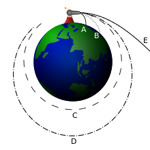
@harambe see:
Newton's cannonball was a thought experiment Isaac Newton used to hypothesize that the force of gravity was universal, and it was the key force for planetary motion. It appeared in his book A Treatise of the System of the World. == Thought experiment == In this experiment from his book (p. 5-8), Newton visualizes a cannon on top of a very high mountain. If there were no forces of gravitation or air resistance, the cannonball should follow a straight line away from Earth, in the direction that it was fired. If a gravitational force acts on the cannonball, it will follow a different path depending...
Cool stuff
@JohnRennie what is the escape velocity value here... It isn't same like that of earth right
@sammygerbil are you free for some physics now even if you are on holiday??
@harambe I have postponed my holiday until tomorrow. If John Rennie is still available it would be better for him to continue. I just came to the chatroom to check something.
Oh okay. I think @JohnRennie is away and it's usually his leaving time. When ever you are free can you ping me
11:31
@sammygerbil ...could you solve my problem now?
@harambe ok I can deal with your question now.
@NehalSamee Yes. Are you asking again about the strange circuit?
@sammygerbil Yeah... It was a part of a continuous circuit...
0
Q: Finding voltage drop across a capacitor

Nehal SameeThe circuit below is a part of a continuous circuit : The question asks to find the voltage drop across the capacitor of 2 microF. The values of the resistances and currents are arbitrary. I only want to confirm if my process is right or not. MY EFFORT: As the currents and directions are g...

Check here if needed...
@sammygerbil
@sammygerbil I will ask after this discussion
@NehalSamee If as you say "the currents and directions are given" then yes your solution (applying KCL then KVL) is correct.
@sammygerbil Thank you so much....
@harambe you can carry on...
11:41
@sammygerbil imgur.com/a/i6MowMt
Q6
@NehalSamee The EMFs and other elements outside of the loop are irrelevant. They might affect the currents coming in and the potentials at each node, but if you are given 3 out of 4 currents at each node then you can deduce the missing current and apply KVL to the loop.
I am kind a stuck here.. No idea how to use COM in gravitational
Do we use com frame here
Here would they exhibit circular motion due to gravitational attraction between them?
@harambe Yes COM frame is best. The motion could be circular or elliptical. If elliptical the separation is not fixed, but the question seems to assume it is, so I think we must assume the 2 orbits are circular.
Okay
11:58
Each star orbits the COM at distances $r_1, r_2$ so the centripetal force on each is $mr_1\omega^2=m_2r_2\omega^2=Gm_1m_2/(r_1+r_2)^2$. You have $D=r_1+r_2$ and $M=m_1+m_2$ also $m_1r_1=m_2r_2$ and $\omega T=2\pi$. Eliminate $r_1, r_2, m_2, m_2$. It should not be difficult.
01:00 - 12:0012:00 - 18:00

« first day (591 days earlier)      last day (2328 days later) »