« first day (1575 days earlier)      last day (3655 days later) » 

Anonymous
05:21
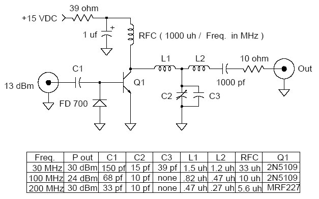
@jippie gonna build this circuit:
Anonymous
Anonymous
currently finding scraps with those specs
Anonymous
why is everything earthed... wat
@PlasmaHH A good place for repair questions is iFixIt.com
Anonymous
@NickAlexeev question about the schematic I just posted... what purpose does the diode labeled as FD-700 (fairchild?) serve in the circuit?
05:47
@PatoSáinz The transistor has no DC bias, which is ... interesting, not to say awkward. I guess the function for the diode is that is sees a (dis)charge path both for positive input half cycle (through the transistor) and for negative input.
Anonymous
@jippie "it's interesting that it has no dc bias"? What does that imply?
It'll also protect the transistor against too high negative input voltages, but avalanche breakdown is usually in the order of 6 or 7 Volts, so not likely that is the reason.
Anonymous
All RF circuits are really complicated to me damn
Anonymous
Anonymous
just look at that 80W behemoth
05:50
@PatoSáinz depends on the input signal, it causes huge distortion. You know a transistor needs approx 0.6 Volt on its base to work, right? If the base voltage is lower than that nothing happens. That also means that part of the input signal is cut off.
Anonymous
@jippie btw the circuit I posted about is an amplifier and it takes input from my FM transceiver output (currently a raspberry pi)
Anonymous
for it to work properly I should also connect the pi's ground pins to the coax's shield right
Is it an amplifier or an modulator?
Anonymous
just an amp
Anonymous
the modulator comes into the transceiver
05:51
let me grab a coffee, I'll check the diagram in a second
Anonymous
thanks
Anonymous
because remember all the mess I had with my relay circuit?
Anonymous
And all of that because I couldn't figure out that I should connect the ground pin of my Pi to the ground of my +12VDC power supply
Anonymous
and this circuit has a shit ton of things that go to earth so I wonder... do I need to connect all earths again? I know EMF flows in a loop and shit but RF is just too dificult to grasp because at the end there's just an antenna which just has a half connected to the coax shield and the other to the core but that's not a proper circuit
@PatoSáinz oh right that was you ... hmm ... The learning curve from driving a relay, connecting grounds together on one side to RF on the other side is a pretty steep one. Don't want to discourage you.
Anonymous
05:55
@jippie I know... but RF is actually why I got into EE altogether heh
@PatoSáinz That is a good reason, I'm just saying you may run into a couple challanges where you have to step back to solve them.
@PatoSáinz all those little forks go to ground, yes. They're all connected together.
Anonymous
@jippie I'm drawing a quick mspaint for what I've got in mind
@PatoSáinz where do you see the half connected coax?
Anonymous
@jippie hang on
Anonymous
Anonymous
06:05
@jippie ^ this is what I have in mind for the wiring
Anonymous
akin to how you helped me make the relay circuit work by showing me I had to have all ground nicely connected to each source's ground
Anonymous
also I'm going to add a Low Pass Filter after that amp later in order to not f*ck up all my spectrum with harmonics but I think I'll just buy one and focus one building one thing right
Depending on the frequency you're aiming at, do remember that all wires have an inductance. The way you draw the connections introduces lots of inductance. This may be an issue at high frequencies, as it basically changes your circuit.
Anonymous
@jippie 100MHz-- not that high, also, yea, the wires are going to be taken care of (and a lot of right angle junctions in order to not couple them), also, I have all the impedance matching issues for Standing Wave Reflections sorted out
Anonymous
now I just have to build the amp
Anonymous
06:11
I wonder why does it need all of those caps and inductors if I could just, in theory use that NPN alone and call it a day i guess
Also, when aiming at approx. 100MHz, the wavelength of your signals is about 3m. That means that long wires in the order of 30cm are actually a delay line and introduce other effects.
Anonymous
@jippie my antenna is tuned and I'm planning to keep all other lengths as short as possible
So you really want to keep very short lines between components.
Anonymous
yea
I like your enthousiasm :o)
Anonymous
06:13
ignorance is bliss they say
Anonymous
I've never seena variable capacitor in my life
Anonymous
@jippie I'll begin building it tomorrow when I finish getting the parts
Anonymous
do you think my sketch's wiring is going to work?
Anonymous
all grounds together
@PatoSáinz surely you did, every cheap radio has one.
Anonymous
06:18
@jippie maybe I mistaked it for a vibrator lol
Anonymous
how stupid
@PatoSáinz It could very well work if the drive signal is large enough (the DC bias thing), but not too large (destroying the transistor) ... if the wires aren't too long, you you have the right components. One challenge you have is that it'll be hard to measure a 100MHz signal for troubleshooting.
where did you find this amp circuit?
Anonymous
@jippie I guess that for troubleshooting I'll just replace the RF input for a plain old... say +5V DC
Anonymous
it's been tested in youtube
Anonymous
06:22
it states it needs at least 13dBm input to work
Anonymous
which is just what my pi can output
@PatoSáinz Ah it is saying same thing as I said, just in other words:
> This is a universal 1 Watt RF class C amplifier that is ideally suited for low power FM transmitters. Input should be at least 100mW to achieve 1W output.
Anonymous
yea
Anonymous
but the schematic says 13 dBm and that's 10mW
Anonymous
so I think it'll work fine too
06:24
class C => for the chopping of the wave form due to DC bias
100mW input for signal strong enough to drive the transistor (again due to no bias)
Anonymous
I couldn't find a more sensitive amp yet but I'm still looking for... but this one seems to be my best bet
distortion will be significant. I hope your neighbors won't complain that their radios stop working when your at home ;o)
Anonymous
@jippie youtube.com/watch?v=vrFLGBU41Ig here's a demo
Anonymous
@jippie yea lol haha
Anonymous
@jippie what distortion do you mean?
Anonymous
06:32
harmonics?
Anonymous
clipping?
@PatoSáinz ...
Anonymous
@jippie uhm sorry o.o
if you put 100 MHz in, you'll get 100, 300, 500, 700, 900, .... MHz out
Anonymous
harmonics then
Anonymous
06:36
yea that's why I'm going to attach a LPF later
@PatoSáinz You'll pull airplanes from the sky if you don't. ;o)
Anonymous
@jippie and probably interfere with some GSM bands
GSM frequency bands or frequency ranges are the cellular frequencies designated by the ITU for the operation of GSM mobile phones. == Bands == There are fourteen bands defined in 3GPP TS 45.005, which succeeded 3GPP TS 05.05: bands 2 and 5 (shaded in blue) have been deployed in NAR and CALA (North American Region [Canada and the US], Caribbean and Latin America) bands 3 and 8 (shaded in yellow) have been deployed in EMEA and APAC (Europe, the Middle East and Africa, Asia-Pacific) all other bands have not seen any commercial deployments P-GSM, Standard or Primary GSM-900 Band E-GSM, Extended GSM...
look at the frequency bands GSM works on.
Anonymous
@jippie 900 band
Anonymous
it's a far harmonic but still there
06:39
You'll notice that the higher band is an integer multiple of the lower band: 450 => 900; 900 => 1800; 850 => 1900.
Anonymous
@jippie saving money on transceivers by having resonance with all bands?
The reason for this, simply said, is: If you mess up your 450MHz GSM transmitters, you'll mess up your own channels in higher frequency bands.
So a manufacturer of a GSM will think two times when designing a 450MHz phone, because he will want to be able to sell 900 and 1800 MHz types later on too.
Anonymous
that's... pragmatic and clever
@PatoSáinz No it's more a thing about not wanting to mess with your own channels.
Similar with amatuer radio bands, or at least in europe. The frequency bands are chosen in such a way that the harmonics of the signal are in the higher amateur band and so on.
Anonymous
@jippie are you, by any chance, a ham?
06:45
@PatoSáinz nope
I have to get into the office early today, so I have to pack.
enjoy your night @PatoSáinz
Anonymous
thanks, you enjoy your morning
10:05
hm, are there any special requirements for sending signals through a rotary transformer vs. static airgap?
 
2 hours later…
11:36
@PlasmaHH A toroidal transformer? no.
11:47
@W5VO no, I mean a rotary transformer like in VHS heads. 15000rpm or so.
12:17
@PlasmaHH hmm... there may be some cross coupling issues between different windings, and it may be have a low saturation limit
may require high frequencies to use effectively
 
4 hours later…
16:42
is there a shorter thing called complement?
shorter word for it
oh ya NOt lol

« first day (1575 days earlier)      last day (3655 days later) »